")


The overall design brief for this project is as follows:
In order to achieve this, there is:
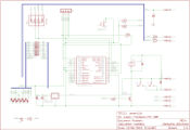
Our original design was a single layer PCB, using a Microchip PIC controller. The use of a PIC has been retained over all iterations - although the actual PIC being used has changed a couple of times.
Each of the 7-segments are controlled by one of the PIC's I/O pins, and the sensors are fed into others.
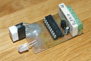
The first two designs used a right-angle LED connector - and that was the most expensive component on the board.
The second iteration changed the way the inputs worked, and added some output protection the client requested (it meant they didn't need to fit it elsewhere in their machine's wiring loom).
However, it did result in a larger PCB.
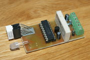
The next design used two PCBs - one for the main circuit board, the other for the LEDs. This made it possible to use larger LEDs, and also make it easier to mount in the dashboard as silicone sealant can be used on the LED PCB.
The client also requested an additional input for a secondary switch that the operator could use. However, this was never actually used.
Unfortunately, all of these complicated the manufacture of the unit - but the cost saving outweighed that.
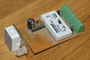
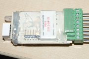
In order to prevent ESD damage to the PCB, this iteration included TVS input protection, and also encasement in heat-shrink tubing.
In addition, a tester was made so the client could test the finished circuit boards.
The client also requested the capability of having a remote display. This meant an additional connection - and when combined with the extra input added to the third iteration, a simple serial protocol could be implemented in order to allow both extra switches and displays.
Neither ended up being implemented though (but the facility is there should the client need it).
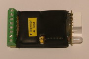
This iteration built on the fourth iteration, where the client wanted a removeable connector, so it would be easy to swap the units if necessary.
The opportunity to change the switch to a small slide switch was taken at the same time, which meant that the hole in the heat-shrink no longer needed to be made.
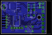
Note that this picture was an experimental model for this, where a 6-pin plug-in connector was used instead of an 8-pin connector (the other two pins being the extension for additional controls/displays which are unused).
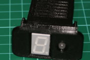
The sixth iteration added a 3D printed case to the design - as well as some minor internal changes. This meant the client no longer had to cut holes into the dashboard blanks. He also no longer needed to glue the display to the dasboard blank.
The case not only allowed the heat-shrink to be removed, it also gave it a significant visual improvement.
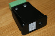
This iteration went back to the "making it easier" approach - it now has a single PCB, and a push-button switch instead of a slide switch. The 3D printed case is still there.
The case is now a two-piece case, instead of the 4-piece for the fifth iteration (with a third piece for the switch extension button).
This is work-in-progress, but is a slight alteration to the seventh iteration, using a more readily available relay, instead of the one that needs the pins bent in order to make it fit.
And, to make it easier, it'll only have a single screw holding the top and the bottom together.
Hopefully this will be the last iteration (although there may be one to use a MOSFET instead of a relay - although that does depend on whether there's the possibility of wiring it in reverse...)